Identifying Your Layout
Identification is crucial before you begin on restoration and it is very easy to jump to conclusions as many of these layouts were very close in their design and specifications. You could end up damaging a layout's authenticity by "restoring" it as something it never was. This is extremely important in the 4x6 layouts offered to dealers in the late 40's and through the mid 50's. Many of them used the same track plans and differed mainly in the accessories included. These usually featured the most recently introduced accessories. In most cases, the accessories are labeled by what appears to be a rubber stamp impression on the bottom of the board, but the labeling can also appear on the top or in the form of stapled tags. These markings are usually accompanied by fahnstock clips tacked to the board for electrical connections.
Gilbert layouts invariably use a squared off wiring style, with the wiring lined up parallel to a side of the board with right angle turns as needed. Diagonal runs are avoided except to when it is the best way to get to accessories. Also, long strips of uncut track pin steel were often used as buss bars.
1. 4x6 issues:
Track Plans
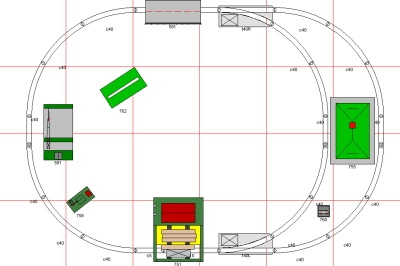
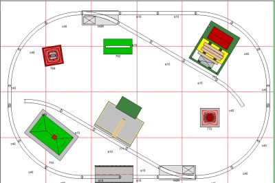
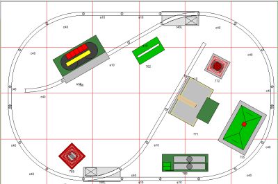
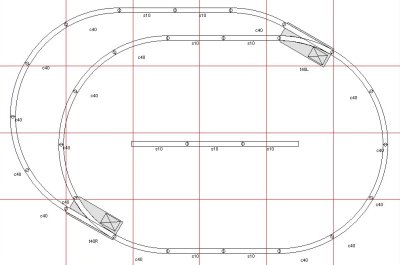
Many 4x6 layouts used the same track plan in different years featuring different accessories, which makes identification of the exact 4x6 layout you have difficult. Face it, there are not many different plans you can do in a 4x6 space. There are basically 4 different loop designs used, as shown below, but the accessories differ from year to year.
 |
 |
|
Oval with Bypass - (Display 98 - 1949) Also used on No's 122 & 133 |
Oval with Spur Tracks - (Display 99 - 1950)
Also used on No. 116 |
 |
 |
|
Oval with One Sharp Spur - (Display 112 - 1951) |
Partial Double Oval (Display 35 - 1953) Also used on No.'s 150, 151, 152, 175, 176, & 177 |
The spur designs provided for excellent display of the operating accessories, but the Oval with Bypass and Partial Double Oval designs allowed two trains to be operated sequentially while storing the other on the bypass. Most of the later layouts were made with the Partial Double Oval track plan, inserting an unconnected display track positioned in the middle to feature one or more operating accessories.
The track plans can give you a guide to use to determine if the layout you have has been changed from its original track plan. If the track has been moved, the original nail holes will remain, giving you a way to determine if the track plan has been changed. This can also be important in identifying the larger 4x8, 5x9, and larger layouts.
Display Shelf Placement
Several different display shelves were used with the 4x6 layouts. In some cases you may have a layout without the display shelf but you can still determine the likely display shelf that accompanied the layout by examining the edges of the layout for screw holes. If the display shelf was a back mounted display, you will see screw holes or bolt holes along one of the 6 ft. sides. If the display was what was called an "Island" display with the shelf, or in some cases, a sign, mounted over the center of the layout, there will be holes at the middle of the 4 ft. sides. Widely spaced holes are unique to the 133 and can be a key in identifying that display.
Even if you receive what appears to be a complete 4x6 layout with display shelf, they could be mismatched. One possible sign of that is an Island display with a center mounted shelf that has supports that seem to get in the way of the track plan, so be sure to check that out.
Features Noted in Illuminated Windows of Display Shelf
The Illuminated display windows changed from year to year, depending on which features Gilbert wanted to highlight. If your display has the translucent signs, check to compare them with the illustrations in the Layout Displays section of this website. Only 1950 displays will note an "Electronic Whistle." In other years it is called an "Air Chime Whistle." Also, "Pul-mor" will only be featured on the displays from after that feature was introduced.
2. Mirrored Track Plans & Size Variations
While these layouts were cataloged and produced more or less according to set layout plans, variations apparently did occur as evidenced by the fact that we see layouts that match a catalog layout, except for the fact that they are a mirror image. On layouts with more than one loop of track there are even layouts where only one of the loops is mirrored. Size variations from the cataloged dimensions have also been found. In many cases they may be a foot or two longer, but they are unmistakenly Gilbert produced layouts.
I doubt that these layouts were constructed in quantity and warehoused while waiting for buyers. Most likely they were built on an as ordered basis. This would allow for size or orientation variations to suit a buyer, much like tract home builders offer reverse floor plans in their model homes to provide variation. Whether these variations were done at the request of the ordering store or were just Gilbert varying the appearance of the layouts to make them more unique is anyone's guess.
3. Equipment Variations
In many cases, the equipment may be slightly different than that listed in the catalog. In addition, the catalog image my not match the list of included equipment. If you look at the catalog listings, you will see that some layouts are quite similar and bear different numbers and were sold in different. The difference is usually in the equipment, and in some cases can be a key to identifying the layout. Another possibility does exist though, as I doubt that retail dealers would buy a whole new layout when it would be a simple thing to just put in the newly introduced accessories if they desired. If they did that, you might see a stockyard marked on the board, but find an animated passenger station instead. There was even one No. 98 layout from 1949 that had rubber roadbed installed by the store when it was introduced the following year.