New York - 1st Floor Layout 3 -
1955 - 1958
The Super Layout
![]()
![]()
![]()

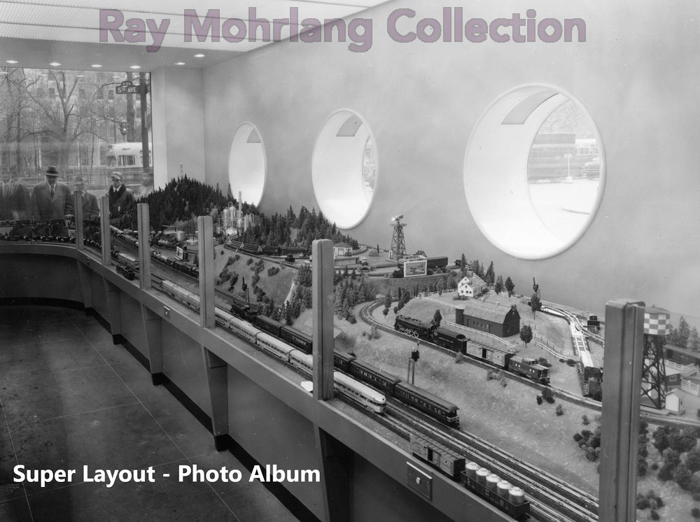 This layout was probably Gilbert's crowning achievement. In shape, it was a reverse "J" with its base at the former 5th Avenue entrance, which was closed to make room for the layout. It was reported to have cost a huge sum to build and the expenditure upset some of the stockholders. 1 2 The Grand Opening of the Layout was held in February 1955. This layout was the last project Frank Castiglione worked on prior to leaving Gilbert to start his hobby shop in Branford, Connecticut. Ray Mohrlang told me that the Yale University Art Department also played a large part in the creation of this layout. He also noted that there were 11 loops of track, with pushbuttons at the side of the layout that could control the trains on the three elevated loops on the long leg of the "J". A triple loop circled the entire layout. The 5th Avenue window display area was built at a lower than normal level, as can be seen in the photo below. According to Frank Castiglione, that was to make it more easily viewable by children. |
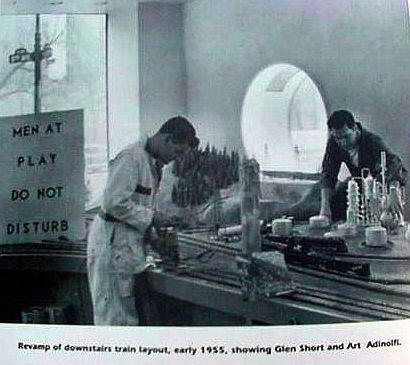 This
photo shows Glen Short and Art Adinolfi putting what appear
to be the final touches on the layout in 1955. Glen
Short was the son of V. Roxor Short, whose name has been
associated as an independent contractor builder of Gilbert
factory layouts sold to dealers. He may well be the
person mis-labeled on a photo of the 1948 Eastern States
Exposition as "C" Roxor Short. The photos fit his
census documented age at the time of both photos.
(Click here for
1948 photo.) This
photo shows Glen Short and Art Adinolfi putting what appear
to be the final touches on the layout in 1955. Glen
Short was the son of V. Roxor Short, whose name has been
associated as an independent contractor builder of Gilbert
factory layouts sold to dealers. He may well be the
person mis-labeled on a photo of the 1948 Eastern States
Exposition as "C" Roxor Short. The photos fit his
census documented age at the time of both photos.
(Click here for
1948 photo.) |
The Ray Mohrlang Collection
Thanks to Ray Mohrlang, we have several photos of this layout to display here. Just click on the photo or the button at the top to view an album of photos of this amazing layout. Judging from the rolling stock that can be seen in these photos, I would guess that they were probably taken in 1955, shortly after the layout opened. Some of Ray's other photos of this layout also appear in two articles by Bruce Manson, in the Train Collectors Quarterly. 1 2
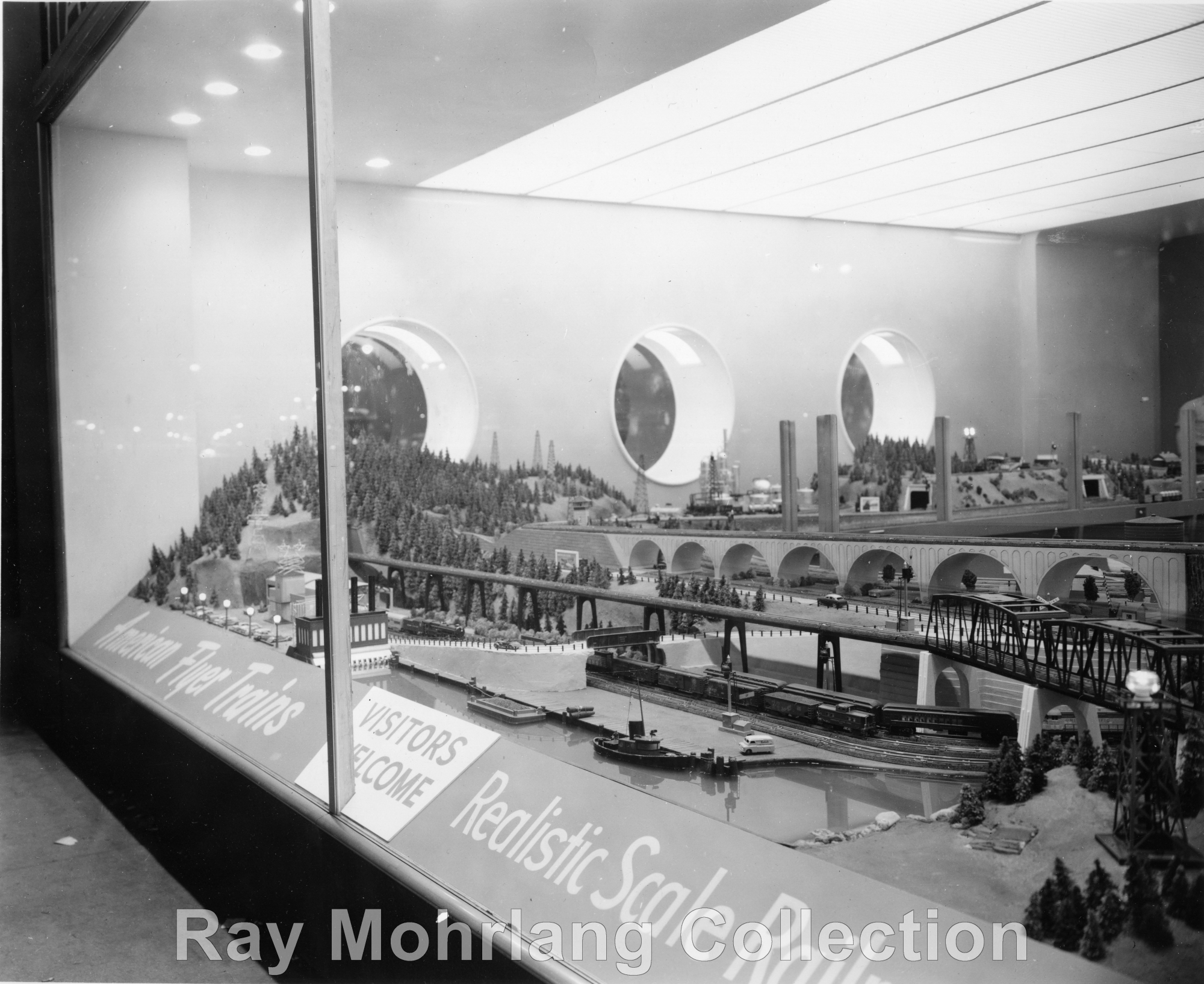
The two photos above appeared in several editions of the Greenberg Guide to American Flyer Trains as well as Bruce Manson's first article on the Hall of Science in the Train Collector's Quarterly in 1980. This led many to believe that the layout was "L" shaped. It wasn't until the next photo appeared in Bruce Manson's follow-up article in 1992 that the true shape of the layout was revealed to be a reverse "J."
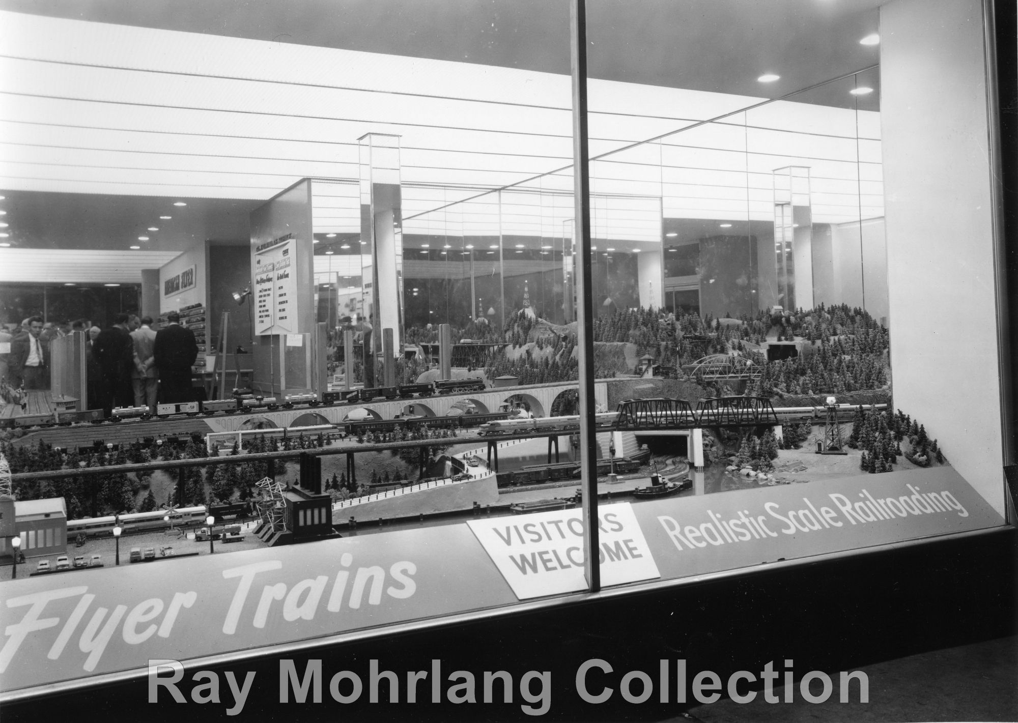
This is one of the few views that demonstrates the fact that the layout was actually a reverse "J" in design as the short end of the "J" is clearly visible on the right. The Waterfall is visible just above the "S" in "Scale." The liberal use of mirrors on the walls surrounding the display makes it difficult to ascertain the exact details of the layout, but at the center of this photo, the HO gauge trestle is visible, though it is quite possibly a reflection of the actual trestle. Also, on the track just below the beginning of the stone arch viaduct, there is an A-A Unit Silver Comet pulling a string of Koppers tank cars. Ray has seen this train in other shots of the layout and believes it was one of several items created especially for this layout.
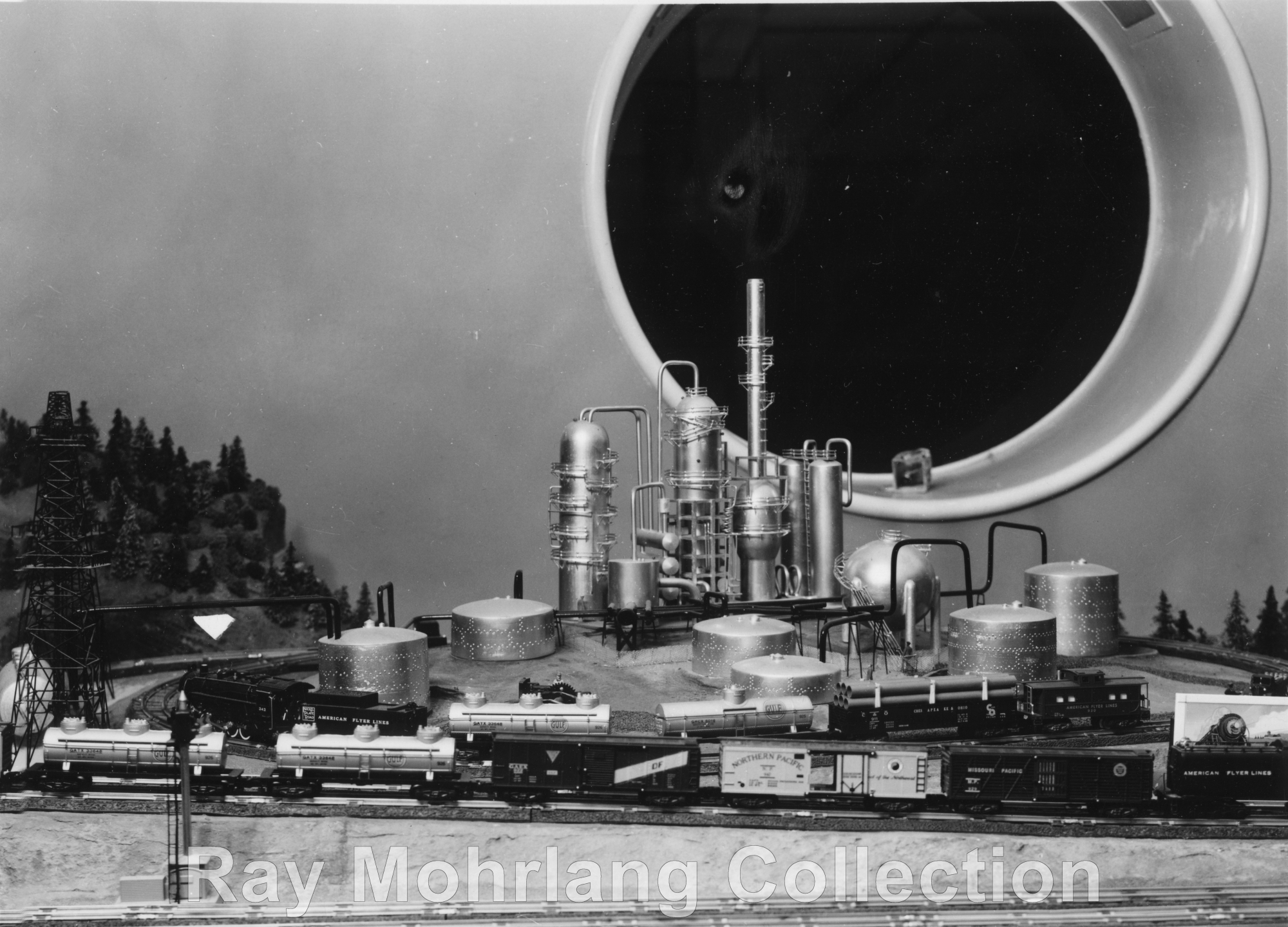
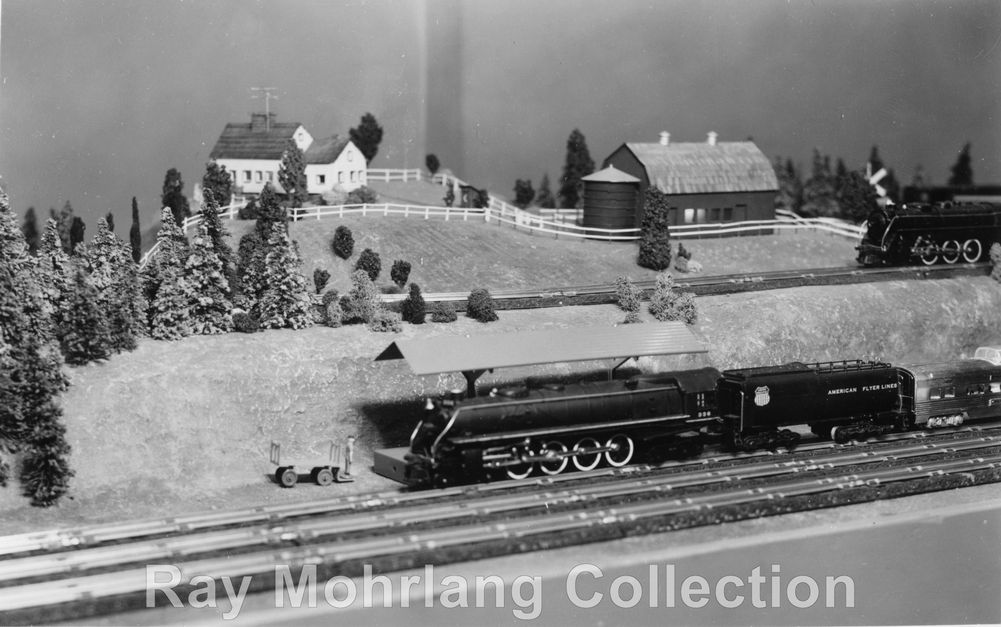
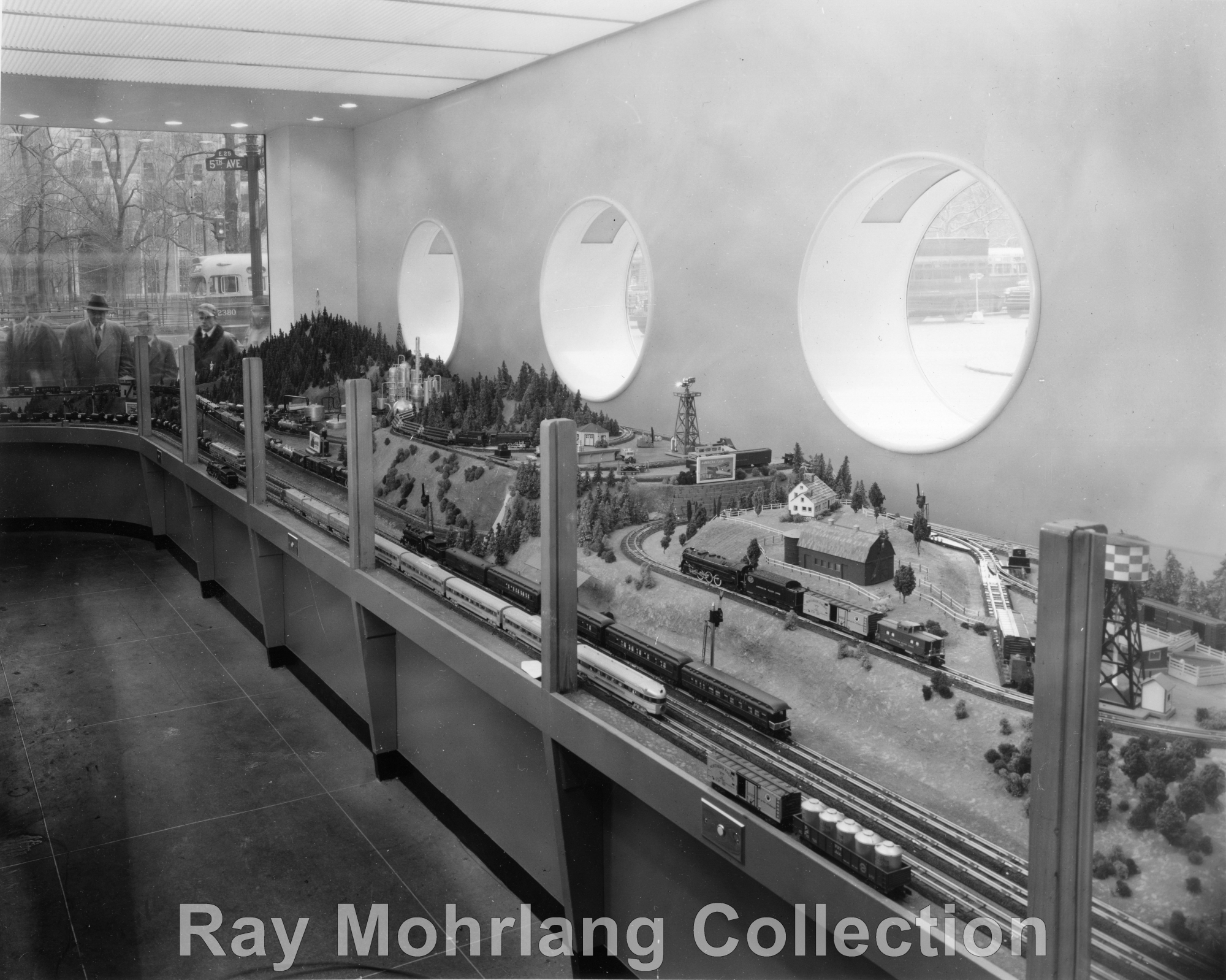
The 25th Street side of the layout consisted of three areas, including the Oil Refinery area (left) and the Farm area (right) Between these was the Mountain area, featuring the lumber industry. Push buttons were placed on the partition that separated viewers from the layout that enabled them to run the trains on these independent loops.
The photos of the areas shown above shows highly detailed scenes built to scale standards. A three track mainline, which can be seen in the second photo, circled the entire layout and went around the front and back of the three areas on the 25th Street side of the building. One of the trademark porthole windows can be seen in the left photo. Three dome tank cars date this photo to the 1955-1957 period.
In addition, a dogbone loop inside the three outer loops also ran down the incline shown here and returned by looping under the logging area to the right and coming back up the incline on the inner track which can be seen in back of the train in this photo. From the photos I have reviewed, I am fairly certain that this dogbone proceeded in double track form over the viaduct shown in the 5th Avenue views. From there it looped around the hill shown in the third photo, below the HO trains on the trestle, with another independent loop within it.
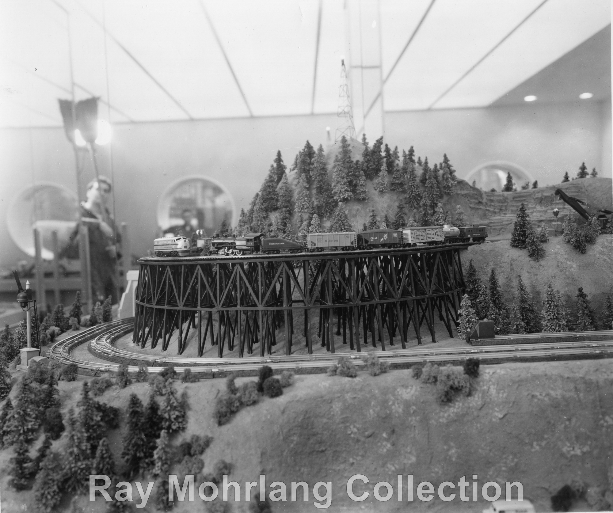 This trestle, clearly built to scale standards, was located at the
tip of the short end of the reverse "J." Judging from the rolling stock,
this photo was probably taken in late 1954 or 1955 at the beginning of the re-introduction of the HO
line. If you look closely at the trains on the trestle, you can see
that the rolling stock differs somewhat from the standard
production models and may be prototypes. The freight is headed up by the 0-6-0,
which is a 155, which dates to 1950, not the 433 made in
1955 and 1956. The cars all appear to be Varney models
but their decoration does not match the decoration of the
Varney production models. To enable the rapid
introduction of the HO line after it had been discontinued
during the Korean war, Gilbert contracted with Varney to
manufacture several styles of cars. These were manufactured only in 1955 and 1956. The
caboose is a reworked version of Gilbert's own pre-Korean
War model, and may also be a prototype. The Diesel is a
Lackawanna F3 and was also manufactured by Varney and only in 1955 and 1956.
Like all the other rolling stock, it too, appears to differ
from the production model of this locomotive and may also be
a prototype. For more details on this rolling stock
click here to read about it on the Gilbert HO Index. The portholes
are reflections of the 25th Street wall in the mirrored wall at the back of this side of
the layout. This trestle, clearly built to scale standards, was located at the
tip of the short end of the reverse "J." Judging from the rolling stock,
this photo was probably taken in late 1954 or 1955 at the beginning of the re-introduction of the HO
line. If you look closely at the trains on the trestle, you can see
that the rolling stock differs somewhat from the standard
production models and may be prototypes. The freight is headed up by the 0-6-0,
which is a 155, which dates to 1950, not the 433 made in
1955 and 1956. The cars all appear to be Varney models
but their decoration does not match the decoration of the
Varney production models. To enable the rapid
introduction of the HO line after it had been discontinued
during the Korean war, Gilbert contracted with Varney to
manufacture several styles of cars. These were manufactured only in 1955 and 1956. The
caboose is a reworked version of Gilbert's own pre-Korean
War model, and may also be a prototype. The Diesel is a
Lackawanna F3 and was also manufactured by Varney and only in 1955 and 1956.
Like all the other rolling stock, it too, appears to differ
from the production model of this locomotive and may also be
a prototype. For more details on this rolling stock
click here to read about it on the Gilbert HO Index. The portholes
are reflections of the 25th Street wall in the mirrored wall at the back of this side of
the layout.The outer S gauge loop below the trestle is probably the return loop of the dogbone that is coming from the viaduct in the first photo. The inner track is probably part of an independent display loop. |
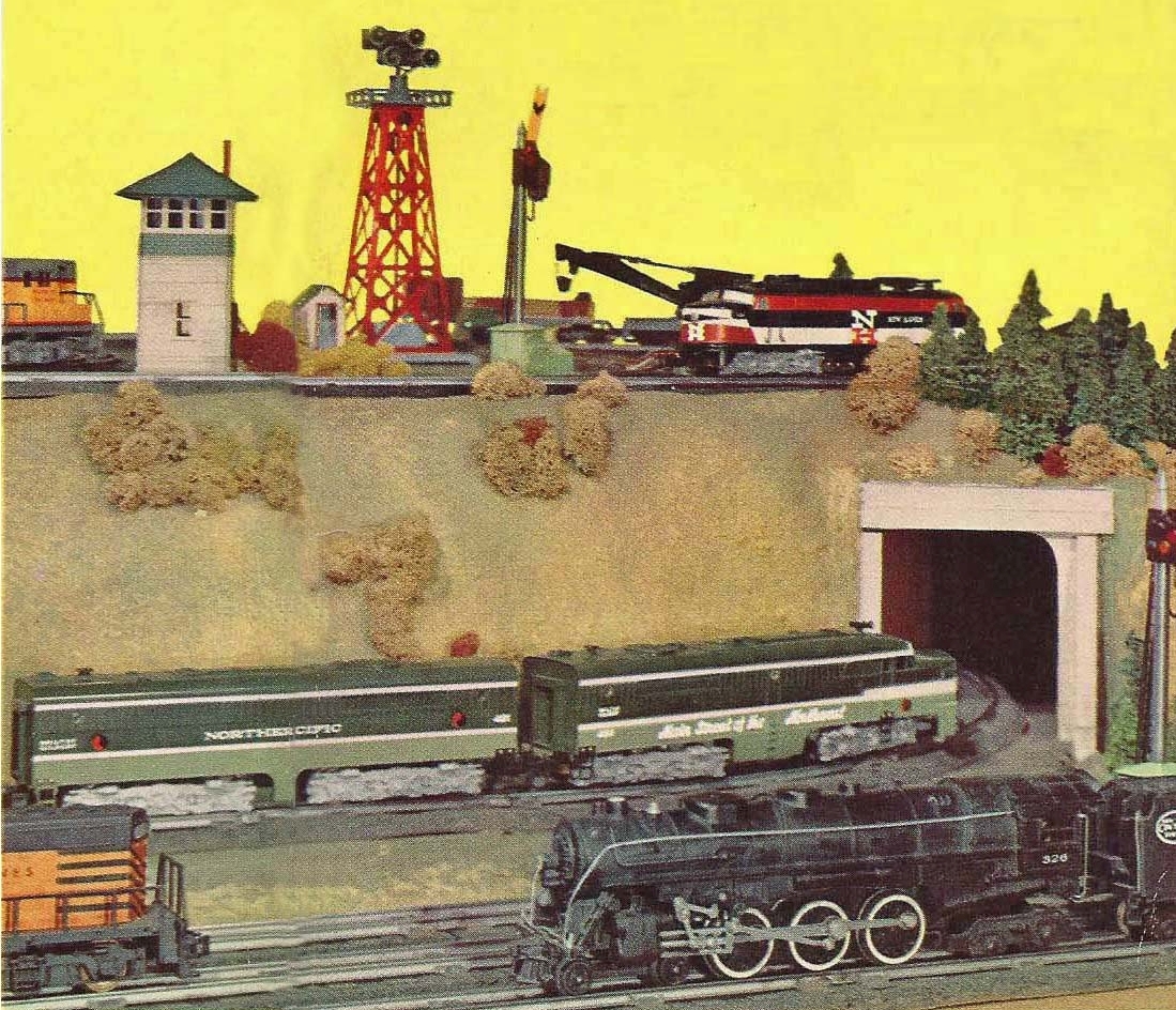
Color Photo From Long Side of Layout - Scan courtesy of Daryl Olszeski
This photo appears on the front and back covers of the 2nd edition of How to Build and Operate a Model Railroad by Marshall McClintock. It has been thought by many to be a shot of a location on the more often photographed 2nd floor layout, but it is clearly a shot taken at the spot on the long side of the layout that was in front of the port hole windows that faced 25th Street. The exact location is the point where the dogbone loop enters a long tunnel to return to the double track viaduct that is visible in photos taken from the 5th Avenue window. The photo presented was created from stitching the images from both covers together. The only problem is that part of the full photo should be on the spine, but isn't, so there is a slight gap between the two images that can be seen mostly in the shortened B unit of the Northern Pacific Diesel.
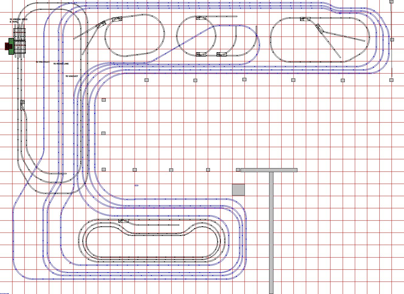
The Track Plan
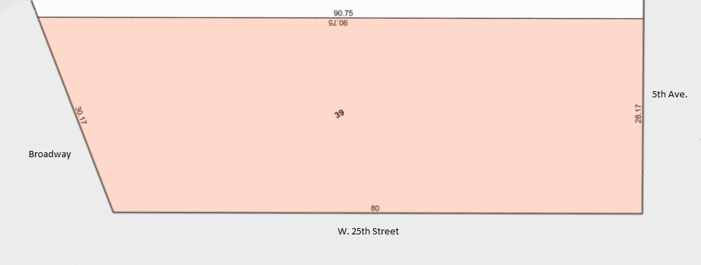
The track plan below is an approximation of the track plan of the Super Layout, which I worked out with the assistance of Richard Trotter and Ray Mohrlang. Based on our observations of the available photos and based on the footprint of the N.Y. Hall of Science as shown on the Manhattan tax maps, (click here to view tax map) we feel this is a reasonable approximation. The track plan was prepared using RRTrack software and uses some wider than normal fixed curves. In keeping with then current layout construction practice, I am sure that Gilbert used the method employed on other layouts of the time, such as the Sibley Department Store layout. On that layout continuous rail mounted on American Flyer ties was bent to custom radii to provide sweeping curves.
There are bound to be errors in the plan shown below, so if you have any other information or photos, please let me know, so we can make this illustration more accurate.
The track plan was recently modified to include wider curves on the five loops that traverse the inside of the reverse "J" at the central area of the track plan. This was based on my discussions with Ray Mohrlang and Richard Trotter shortly before Ray's death. Click on the track plan image below to see a full page view of the track plan.
I believe that it is most likely
that the two tracks that go through the train shed on the Fifth
Avenue side of the layout were two separate loops, based on accounts
claiming that the layout had 12 loops of track. The four long
distance loops that encircle large portions of the layout are shown
in blue to make it easier to follow and distinguish them from those
partially hidden loops from the Fifth Avenue portion of the layout. It is
possible the there could have been one loop with dogbone ends
hidden under the higher parts of the layout inside the store, but
that would make only 11 loops.
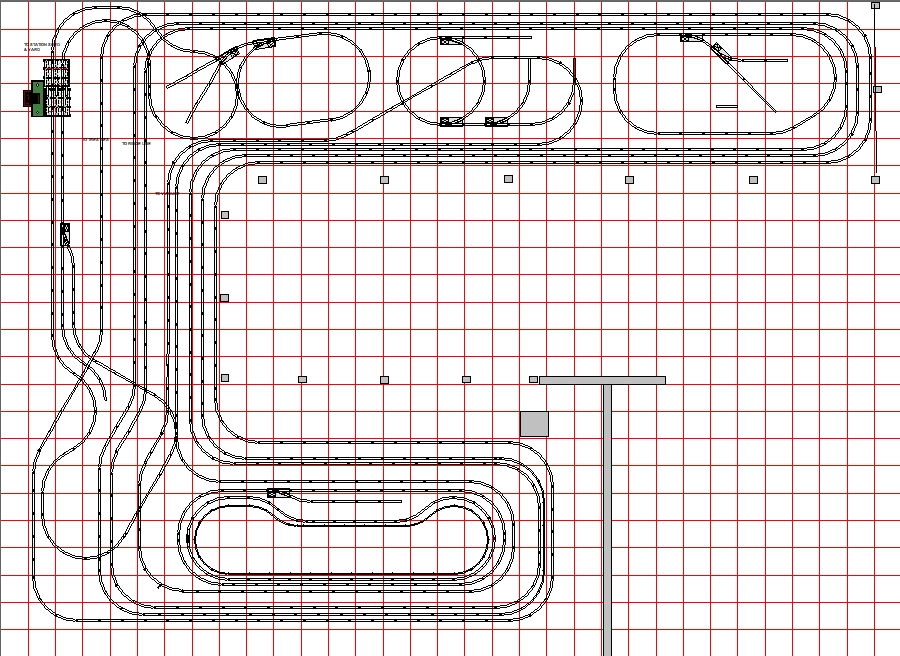
Click here to see the previous track plan version that shows
what I now consider to be an unlikely dogbone track.
Download the
RRtrack file of this track plan for use with your copy of RRtrack software
After the Hall of Science
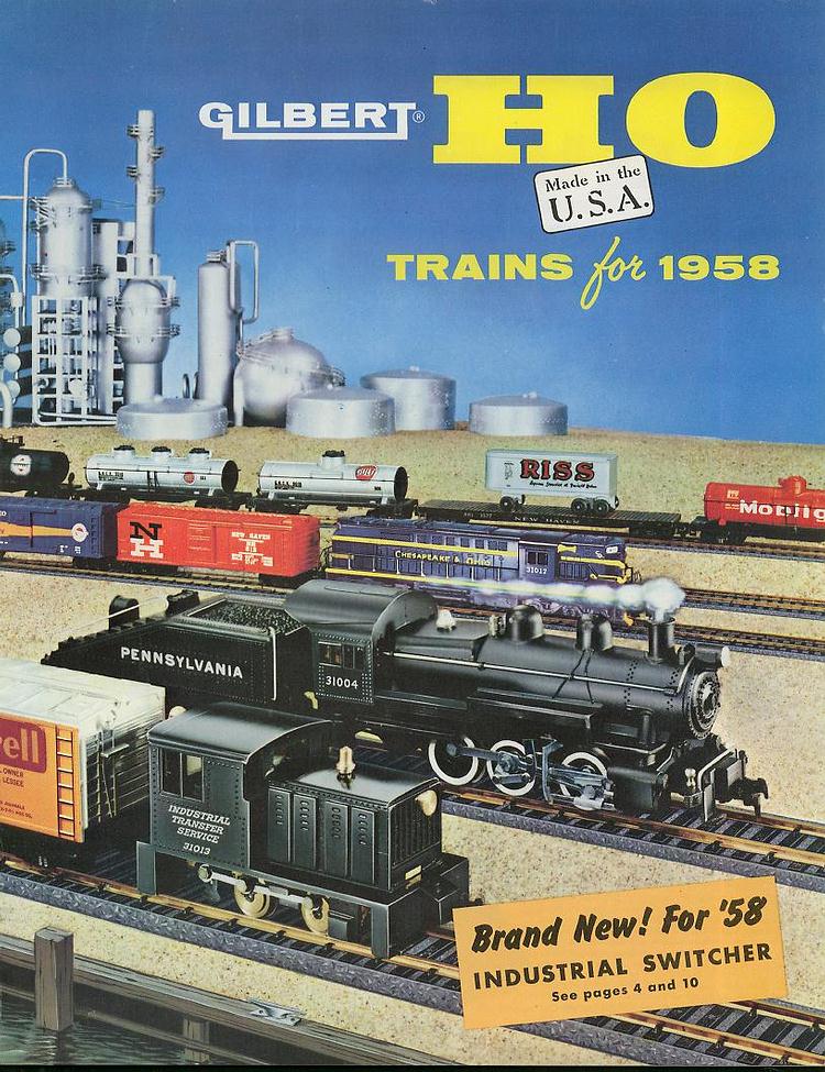 We
know that the Gilbert Hall of Science closed in 1958 and this layout
was presumably dismantled, but one part of it was repurposed, as we
can see from looking at the 1958 HO catalog. In the cover photo on
that catalog, the oil field tanks and towers from this layout have
been rearranged in the background, but it is obvious where they came
from. A part of the layout lived on, if ever so briefly. (Catalog
cover courtesy of myflyertrains.net) We
know that the Gilbert Hall of Science closed in 1958 and this layout
was presumably dismantled, but one part of it was repurposed, as we
can see from looking at the 1958 HO catalog. In the cover photo on
that catalog, the oil field tanks and towers from this layout have
been rearranged in the background, but it is obvious where they came
from. A part of the layout lived on, if ever so briefly. (Catalog
cover courtesy of myflyertrains.net) |
Notes
1
"The Gilbert Hall of
Science," by
Bruce Manson, with Maury Romer - Train Collector's Quarterly, Fall 1980, Vol. 26, No. 5,
page 11 (Photos of this layout throughout the article)
Link to this issue
and article in the TCQ (available to TCA members only)
2
"The Gilbert Hall of Science - Update and Then Some," by Bruce Manson -
Train Collector's Quarterly,
October 1992, Vol. 38, No. 5, page 28 (Photos of this layout throughout the article)
Link to this issue
and article in the TCQ (available to TCA members only)